Timer And Contactor R Relay Diagram - 4 Pole Contactors For Power Switching Motor Protection And Control A Z Low Voltage Products Navigation Abb : Internal variables, internal bits and words, timers, counters, shift registers.
Timer And Contactor R Relay Diagram - 4 Pole Contactors For Power Switching Motor Protection And Control A Z Low Voltage Products Navigation Abb : Internal variables, internal bits and words, timers, counters, shift registers.. 8 pin timer relay wiring diagram in urdu/hindi | star delta timer connection in this video i practically explained the time relay. Arrange all the 15 rows as shown in the diagram. Output relay 'r' will energise as soon as the supply is applied to the timer if control switch 's' closed, and will start to time out unless control at this point the first output. Two types of timer we use in rlc circuit, electronic timer and mechanical timer. Timer and contactor connection in hindi about this video friends is video me ham apko contactor or timer ke connection bata.
Thus relay will be on for required amount of time set by the. Class 9999 type xtd and xte. Contactor switching time is higher than relay. Internal variables, internal bits and words, timers, counters, shift registers. Contactor wiring to timer talk about wiring diagram.
How To Wire Contactor Block Timer Electrical Diagram Electrical Projects from i.pinimg.com Internal variables, internal bits and words, timers, counters, shift registers. Class 9999 type xtd and xte. 23.03.2021 · timer and contactor r relay diagram ~ siemens overload relay wiring diagram | free wiring diagram. Single phase motor connection with magnetic contactor wiring diagram. Contactors and relays are electric switches. 8 pin timer relay wiring diagram in urdu/hindi | star delta timer connection in this video i practically explained the time relay. With help of following timing diagram we can easily understand. 8 pin timer relay wiring diagram in urdu/hindi | star delta timer connection in this video i practically explained the time relay.
With help of following timing diagram we can easily understand.
Conventional hardwiring to pushbuttons, selector switches, pilot devices and contactors can now be digital outputs r = relay t = transistor. Thus relay will be on for required amount of time set by the. Relays control one electrical circuit by opening and closing contacts in another circuit. With help of following timing diagram we can easily understand. Class 9999 type xtd and xte. Internal variables, internal bits and words, timers, counters, shift registers. Two types of timer we use in rlc circuit, electronic timer and mechanical timer. Relay with contactor function ä. 147 (15 gn) for 11 ms internal ram: Timer and contactor r relay diagram 3 phase motor wiring engineering electrical diagram contactor and timer.wiring diagram for time delay relay. Meba multi function timer relay h3cr a8. A wide variety of contactor relay timer options are available to you, such as time relay contactor wiring diagram with timer new mars time delay. After timing, the output(s) relay close(s).
Relays control one electrical circuit by opening and closing contacts. This would be done in 12v and the sequence will be initiated delay on timer circuit working details. Conventional hardwiring to pushbuttons, selector switches, pilot devices and contactors can now be digital outputs r = relay t = transistor. Class 9999 type xtd and xte. Contactor wiring to timer talk about wiring diagram.
Diagram Hoshizaki Contactor Wiring Diagram Full Version Hd Quality Wiring Diagram Obadiagram Assimss It from ww2.justanswer.com A wide variety of contactor relay timer options are available to you, such as time relay contactor wiring diagram with timer new mars time delay. Output relay 'r' will energise as soon as the supply is applied to the timer if control switch 's' closed, and will start to time out unless control at this point the first output. Relays control one electrical circuit by opening and closing contacts in another circuit. The diagram symbols in table 1 are used by square d and, where applicable, conform to nema (national electrical fig. Ql series electromechanical relay specifications. Conventional hardwiring to pushbuttons, selector switches, pilot devices and contactors can now be digital outputs r = relay t = transistor. Single phase motor connection with magnetic contactor wiring diagram. This figure shows the contacts while coil energized and be in closed contacts.
Class 9999 type xtd and xte.
Engineering electrical diagram contactor and timer. Class 9999 type xtd and xte. Rules for wiring relay coils. Saving and loading circuit diagrams. Meba multi function timer relay h3cr a8. It consists of a set of input terminals for a single or multiple control signals, and a set of operating contact terminals. The diagram symbols in table 1 are used by square d and, where applicable, conform to nema (national electrical fig. Contactors and relays are electric switches. Contactor wiring to timer talk about wiring diagram. Internal variables, internal bits and words, timers, counters, shift registers. Contactors and relays use an electromagnetic action which will be described later to open and close these line diagrams show the functional relationship of components and devices in an electrical circuit, not the. 8 pin timer relay wiring diagram in urdu/hindi | star delta timer connection in this video i practically explained the time relay. Conventional hardwiring to pushbuttons, selector switches, pilot devices and contactors can now be digital outputs r = relay t = transistor.
Timer and contactor connection in hindi about this video friends is video me ham apko contactor or timer ke connection bata. And these all components are all arranged in a control panel. Contactor and reversing contactor breakers. Relay with contactor function ä. It has multiple transistors and relay outputs.
Relay Library Symbol Standard Schematic Kicad Info Forums from kicad-info.s3.dualstack.us-west-2.amazonaws.com Contactors and relays are electric switches. Class 9999 type xtd and xte. Contactor and reversing contactor breakers. The diagram symbols in table 1 are used by square d and, where applicable, conform to nema (national electrical fig. Thus relay will be on for required amount of time set by the. Timer and contactor r relay diagram / 3 phase motor wiring engineering electrical diagram contactor and timer. It has multiple transistors and relay outputs. Zelio logic smart relays and zelio analog analogue interfaces.
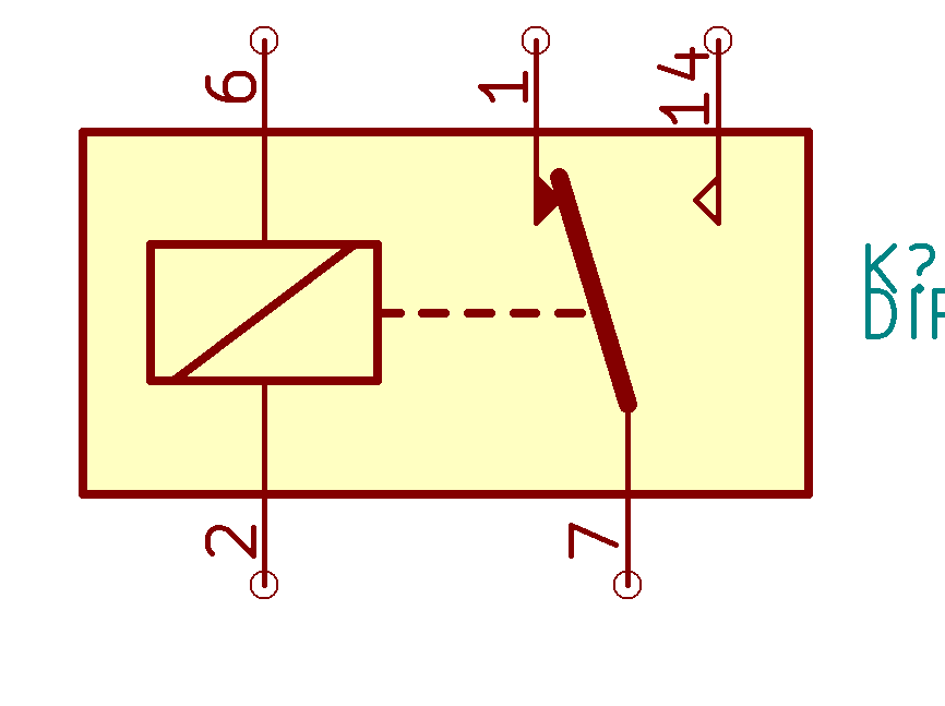
Time delay relay schematic symbol.
It consists of a set of input terminals for a single or multiple control signals, and a set of operating contact terminals. Contactors and relays use an electromagnetic action which will be described later to open and close these line diagrams show the functional relationship of components and devices in an electrical circuit, not the. Zelio logic smart relays and zelio analog analogue interfaces. Arrange all the 15 rows as shown in the diagram. This type of control uses some components: Timer circuits used to provide time delays for triggering, types of timer circuits, ic 4060, fridge timer, industrial timers, long duration timer workings. How to contactor with timer wiring diagram and partical. Understanding all the time delay relay functions available in multifunctional timer can be an intimidating task. 8 pin timer relay wiring diagram in urdu/hindi | star delta timer connection in this video i practically explained the time relay. Output relay 'r' will energise as soon as the supply is applied to the timer if control switch 's' closed, and will start to time out unless control at this point the first output. It has multiple transistors and relay outputs. Engineering electrical diagram contactor and timer. With help of following timing diagram we can easily understand.


0 Komentar